
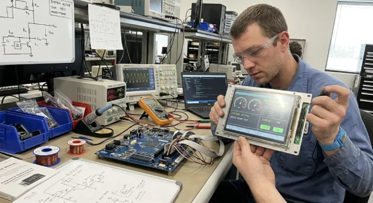
When your prototype display works on the bench but fails after installation in the equipment cabinet, the problem is rarely obvious. The display might become hard to read under bright light, the touch response may degrade in temperature extremes, or the mounting holes may not align with the enclosure cutout. Choosing an industrial TFT LCD display requires matching the specification to the actual operating environment, not just comparing datasheet numbers.
What Makes an Industrial TFT LCD Different?
Display Module vs. Bare LCD Panel
An industrial TFT LCD display can refer to either a bare LCD panel or a complete display module. A bare panel includes the liquid crystal cell, backlight, and driver IC, but requires external controller hardware, display buffer memory, and firmware to generate video signals. A display module integrates additional components: an embedded CPU, flash memory for graphics and configuration data, touch controller, and a communication interface such as UART or SPI.
The architectural difference affects system design. A bare panel typically connects to a host MCU through parallel RGB, LVDS, or MIPI interfaces that require continuous refresh. The host MCU must allocate memory for the frame buffer, handle pixel-level drawing operations, and manage display timing. A display module with an embedded controller handles these tasks internally. The host MCU sends higher-level commands or data rather than managing individual pixels. This can reduce firmware complexity on the MCU side, but requires checking whether the module’s command set, response time, and GUI design tools fit the project requirements.
For example, if the system uses an STM32 or Arduino-based controller with limited memory, offloading display management to an intelligent module can free MCU resources for other control tasks. However, the module must support the required update rate, touch input response, and communication protocol. A module that works well in one application may introduce delays or compatibility issues in another.
What Changes in an Industrial Environment
Temperature range, vibration, dust, humidity, and long operating hours separate industrial equipment from consumer products. A consumer display might specify 0°C to 40°C, while industrial equipment may require -20°C to 70°C or wider. Liquid crystal response slows at low temperature, and some panel technologies stop functioning entirely below a threshold. Backlight brightness also decreases in cold conditions. At high temperature, the panel lifespan shortens and the backlight degrades faster.
Vibration affects mounting. A display installed in mobile equipment or machinery with reciprocating motion needs secure mechanical attachment and shock absorption. Loose mounting can damage connectors, crack solder joints, or allow the panel to shift inside the bezel. Dust and moisture require sealed enclosures, which then create thermal management problems. The display generates heat, and the sealed cabinet traps it.
Operating hours matter for backlight life. A consumer display might run a few hours daily, but industrial equipment may operate 12 to 24 hours per day. LED backlights degrade over time, and brightness decreases. A display specified for 50,000 hours at 25°C may have significantly shorter life at 60°C inside a control cabinet. Checking the actual thermal conditions during extended operation helps avoid premature backlight failure or display replacement during the equipment’s service life.
Specifications That Affect Real-World Selection

Display Size
Physical size determines readability and mounting constraints. A 5-inch display may fit inside a compact instrument panel, but text and icons must be large enough to read at the operator’s working distance. A 10-inch display improves readability but requires more panel cutout space, increases power consumption, and may create problems if the cabinet layout has already been designed.
Diagonal size alone does not define usability. Resolution, aspect ratio, and pixel density also matter. A 7-inch display with 800×480 resolution provides approximately 133 pixels per inch. Text and controls designed for that density may look different on a 10-inch panel with the same resolution, because pixel pitch increases. Conversely, a 7-inch display with 1024×600 resolution offers higher pixel density, which can improve text clarity but requires checking whether the GUI design tools and graphics assets support the resolution.
Mounting dimensions and bezel design affect mechanical integration. Two 7-inch displays with different manufacturers may have different hole patterns, bezel widths, and panel thicknesses. Changing the display model late in the project can require redesigning the enclosure or front panel, which delays production and increases cost.
Brightness and Outdoor Readability
Brightness is measured in nits or candelas per square meter. A typical indoor industrial display provides 300 to 500 nits, which is adequate for controlled lighting. Outdoor or high-ambient-light applications may require 800 to 1000 nits or more. However, brightness alone does not guarantee readability.
Reflections, viewing angle, and cover glass affect what the operator actually sees. A high-brightness display with a glossy surface may reflect overhead lights or sunlight, reducing contrast. Anti-glare or anti-reflective coatings help, but they can also reduce brightness slightly. Viewing angle affects color shift and contrast. A display with narrow viewing angles may look acceptable when viewed straight-on but become hard to read when the operator stands to the side or looks down at the panel.
An outdoor EV charger provides a useful example. The display must remain readable in direct sunlight, but the installation angle, time of day, and reflections from the charger housing all affect visibility. A 1000-nit display mounted vertically may perform well in morning light but become difficult to read at noon when the sun is directly overhead. Tilting the display slightly or adding a hood can improve readability without increasing brightness. Testing the display under actual lighting conditions during different times of day reveals problems that are not obvious from the specification.
Brightness also increases power consumption and heat generation. A 10-inch display at 1000 nits may consume 15 to 20 watts or more, depending on backlight efficiency. That heat must dissipate inside the enclosure. In a sealed outdoor cabinet, the internal temperature can rise significantly, which then affects the display’s operating temperature range and lifespan.
Operating Temperature
Operating temperature range defines where the display can function reliably. A standard industrial display might specify -20°C to 70°C, but performance changes across that range. Liquid crystal response time increases at low temperature, causing slower image updates or ghosting. Some displays include heaters to keep the panel above a minimum temperature during startup in cold environments, but the heater increases power consumption and requires additional control circuitry.
Storage temperature is not the same as operating temperature. A display that can be stored at -30°C may only operate reliably down to -20°C. If the equipment must power on immediately after cold storage, the display may not initialize correctly or may show distorted images until it warms up. Adding a startup delay or preheat cycle can prevent this, but it affects system behavior and user experience.
High-temperature operation reduces backlight life and can cause liquid crystal degradation. A display operating continuously at 60°C will age faster than the same display at 40°C. If the equipment generates heat from motors, power supplies, or other components, measure the actual temperature inside the cabinet during extended operation rather than assuming the display will stay within the specified range. Adding ventilation, relocating heat sources, or selecting a display with a wider temperature range may be necessary.
Touchscreen
Resistive and capacitive touchscreens have different strengths. Resistive touch responds to pressure, so it works with gloves, styluses, or any object that can press the surface. However, resistive touch layers reduce optical clarity and brightness, and the surface can wear out over time. Capacitive touch provides better optical performance and supports multi-touch gestures, but it requires bare fingers or conductive gloves. Water droplets, dirt, or thick gloves can interfere with capacitive touch.
Industrial equipment often operates in conditions where resistive touch is more reliable. A control panel in a factory, outdoor equipment, or machinery where operators wear gloves benefits from resistive touch. However, resistive touchscreens require calibration and may drift over time, especially after temperature changes or mechanical stress. Capacitive touch is more stable and requires less calibration, but environmental interference can make it unreliable in wet or dirty conditions.
Touch controller integration also matters. Some display modules include the touch controller, USB or I2C output, and calibration software. Others provide only the touch panel, and the host system must include the controller, driver software, and calibration tools. Checking which components are included and whether the communication interface matches the system architecture prevents integration problems late in the project.
How to Choose the Right Industrial TFT LCD Display
Start With the Application Environment
Before comparing display specifications, document the operating conditions: ambient temperature range, lighting, vibration, exposure to dust or moisture, expected operating hours per day, and operator working distance. Measure or estimate the thermal conditions inside the enclosure during normal operation, not just ambient air temperature.
Identify readability requirements. Will the operator view the display from directly in front, or from the side? Does the equipment operate outdoors, under overhead lights, or in a dark enclosure? Will the operator wear gloves? Does the application require color differentiation, or is monochrome acceptable? Answering these questions narrows the acceptable display technologies, brightness levels, and touchscreen types before looking at specific products.
Check whether the display must pass any environmental or safety standards. Some industries require UL, CE, or IP ratings. A display without the required rating may perform well technically but create certification problems later.
Check Interface and Controller Compatibility
The communication interface between the display and the host system affects firmware development, data throughput, and system architecture. A bare LCD panel with RGB, LVDS, or MIPI interface requires the host MCU to continuously refresh the display and manage all pixel operations. This works well if the host already has a display controller, sufficient memory, and processing power. It provides maximum flexibility for custom graphics but requires more firmware development.
A display module with UART, SPI, or I2C interface simplifies host-side firmware but requires checking the module’s command set, response time, and whether the module can handle the required update rate. For example, a UART-based display module might work well for relatively static screens with occasional updates, but it may not support smooth animation or high-frequency data updates. If the system needs to refresh a waveform, graph, or rapidly changing data field, verify the module’s update rate under realistic data loads before committing to the design.
When using an intelligent display module, check whether the GUI design tools support the required graphics formats, fonts, languages, and control types. Some modules provide Windows-based design software with drag-and-drop GUI editors. Others require manual configuration files or scripting. The design tools should fit the team’s workflow and skill set. A module with excellent hardware but poor software support can slow down development.
An industrial control panel illustrates this trade-off. The equipment uses an STM32 MCU for motor control, sensor data acquisition, and communication. Adding a display requires showing real-time data, alarm messages, and a settings menu. Using a bare LCD panel with RGB interface would require allocating a large portion of the STM32’s flash and RAM for display management, reducing resources available for control tasks. An intelligent display module with UART interface offloads display management and allows the STM32 to focus on control functions. However, the module’s command set must support the required data update rate, and the UART baud rate must be fast enough to avoid visible delays when updating multiple data fields.
Confirm Mounting and Mechanical Requirements
Panel cutout dimensions, mounting hole locations, and connector placement affect enclosure design. Obtain a mechanical drawing early in the project, not just electrical specifications. If the enclosure or front panel has already been designed, check whether the display will physically fit before ordering samples.
Connector type and location matter during installation and maintenance. A display with a connector on the back may be easy to mount but difficult to access for cable replacement or debugging. A side-mounted connector may simplify access but create cable routing problems inside a tight enclosure. Ribbon cables are common but can be fragile. If the equipment experiences vibration, check whether the connector has locking features or requires additional strain relief.
Bezel design affects ingress protection. A display with a sealed front bezel and gasket can achieve IP65 or higher when mounted correctly, but the mounting surface must be flat and clean. If the front panel has texture, paint, or irregularities, the gasket may not seal properly. Rear-mounted displays without front sealing require the enclosure itself to provide protection.
Consider Integration and Long-Term Supply
A display that works well in the prototype phase may become unavailable during production, or the manufacturer may discontinue the model. When selecting a display, check the supplier’s product lifecycle information and whether a compatible replacement exists if the model is discontinued. Comparing established LCD display manufacturers can also help when evaluating product availability, technical support, and long-term supply.Some suppliers offer long-term supply commitments for industrial products, but this varies by manufacturer and product line.
Sample availability and lead time affect project schedules. A display with excellent specifications but six-month lead time creates risk if the project has tight delivery deadlines. Starting qualification early and ordering production quantities in advance reduces risk, but it requires confident selection decisions. If the project is still in the prototype stage and specifications may change, prioritize displays with good availability and flexible minimum order quantities.
Technical support and documentation quality affect integration speed. A display with incomplete datasheets, unclear command descriptions, or no application examples takes longer to integrate. Supplier responsiveness matters when problems appear during development. Waiting weeks for technical answers delays the project.
For example, STONE Technologies provides intelligent TFT LCD display modules that integrate the display panel, touch controller, embedded CPU, memory, and UART communication interface into a single hardware unit. The modules include GUI design software and command sets for configuration and control. Because the module handles display management internally, the host MCU—such as an STM32, Arduino, or similar controller—sends higher-level commands rather than managing pixel operations and refresh timing. This architecture can reduce firmware development work and simplify integration, but the module’s capabilities, command set, and update rate must match the application requirements. Checking the module’s specifications, design tools, and communication architecture against the project requirements prevents compatibility problems during integration.
Common Selection Mistakes
Choosing Brightness by Specification Alone
A 1000-nit display looks impressive on a datasheet, but brightness alone does not determine readability. Viewing angle, anti-glare coating, installation angle, and ambient light reflections all affect what the operator sees. A 1000-nit display with a glossy surface installed in direct sunlight may be harder to read than a 500-nit display with anti-reflective coating and a slight installation tilt.
Testing under actual conditions reveals problems that specifications do not predict. If possible, install a sample display in the equipment or a similar environment and check readability at different times of day, from different viewing angles, and under different lighting. Brightness can also be reduced in software to save power if the full rating is not needed, but you cannot increase brightness beyond the hardware limit.
Checking the LCD but Not the Controller
An intelligent display module includes both the LCD panel and an embedded controller. Testing the LCD’s brightness, resolution, and touch response does not guarantee that the controller will handle the required update rate, command sequence, or data throughput. Some modules perform well with static screens but slow down when updating multiple fields rapidly. Others may have command set limitations that require workarounds in the host firmware.
During the first prototype build of a vending machine controller, the display updated correctly when showing static product images and prices. However, when the system began processing transactions and updating inventory counts, status messages, and payment information simultaneously, the display refresh slowed noticeably. The LCD itself was fine. The embedded controller in the module could not handle the number of serial commands being sent in quick succession. The development team had tested the display with simple screens but not under realistic transaction loads. Returning to the controller’s command buffer and timing requirements revealed the bottleneck. Reducing the update frequency for non-critical fields and batching commands where possible improved performance, but it required additional firmware development that was not originally planned.
Leaving Mechanical Integration Until the End
Electrical integration often happens first, but mechanical fit can stop production if problems appear late. Panel thickness, mounting hole alignment, connector clearance, and cable routing all need verification before finalizing the enclosure design. A display that fits electrically but does not fit mechanically requires redesigning the front panel, which delays production and increases tooling costs.
Check the mechanical drawing and panel thickness early. If the enclosure design is already complete, confirm that the display will fit before ordering production quantities. If the display has multiple mounting options, choose the one that provides the best connector access and cable routing for the specific enclosure layout.
Common Industrial Applications
Industrial TFT LCD displays appear in equipment that operates under demanding conditions for extended periods. Control panels in manufacturing equipment display machine status, production counts, alarm messages, and operator controls. The display must remain readable under factory lighting, resist vibration from machinery, and operate reliably during long shifts. Touchscreen interfaces reduce the need for physical buttons, but the touch technology must work with gloves and survive repeated use.
EV chargers require outdoor-rated displays with high brightness, wide temperature range, and sealed enclosures. The display shows charging status, payment information, and fault messages. Readability under direct sunlight is critical, but the installation angle and reflections from the charger housing affect visibility. Touch input must work in rain, and the display must survive temperature extremes between summer heat and winter cold.
Vending machines and intelligent lockers use displays for product selection, payment processing, and inventory management. The display operates in unattended environments, so reliability and ease of maintenance matter. Touch input must be intuitive for users unfamiliar with the equipment, and the display must handle varying lighting conditions from indoor lighting to storefront windows with direct sunlight.
Precision instruments, medical equipment, and test equipment use displays for data visualization, waveforms, and control interfaces. These applications require accurate color reproduction, high resolution, and stable performance. The display must not introduce noise into sensitive measurements, and brightness must be adjustable for different viewing environments without affecting measurement accuracy.
Conclusion
An industrial TFT LCD display must match the operating environment, not just the specification sheet. Temperature range, brightness, mounting constraints, interface compatibility, and long-term availability all affect whether the display will work reliably in the equipment. Testing under realistic conditions during the prototype phase reveals problems that are not obvious from datasheets.
Choosing between a bare LCD panel and an intelligent display module depends on the host system’s capabilities, firmware resources, and integration timeline. A bare panel provides flexibility but requires more development work. A display module simplifies integration but requires checking the controller’s capabilities and communication architecture.
If you are still evaluating displays and narrowing down specifications, focus on the actual operating conditions and integration requirements rather than comparing individual numbers. If the project has reached repeated integration failures, late-stage mechanical fit problems, or delivery pressure, technical support from a supplier with experience in similar applications can help identify the bottleneck and reduce further iteration.