
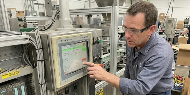
Your HMI display touch screen was working fine in the lab. Then it hit the factory floor — and within three weeks, operators are complaining about ghost touches, the screen goes dark when the ambient temperature drops below 5°C, and your MCU is throwing UART timeout errors you’ve never seen before. Sound familiar?
This isn’t a component defect in the traditional sense. Most of the time, it’s a selection mismatch that didn’t show up until the environment turned real. After 15 years of working on TFT LCD integration projects — from EV charger rollouts in northern China winters to vending machine deployments in humid Southeast Asian markets — I’ve seen this pattern repeat more than I care to count. The goal of this guide is to help you avoid it.
What Is an HMI Display Touch Screen?
At its core, an HMI display touch screen combines three things in one unit: a TFT LCD panel, a touch input layer, and an onboard CPU with flash memory. You talk to it through a UART serial interface. Your MCU sends commands, the display renders the UI, the operator touches the screen, and the module sends back the input event. That’s the loop.
No operating system. No framebuffer driver. No touchscreen daemon to configure. The module handles all of that internally.
The hardware anatomy matters when you’re doing integration:
- Onboard CPU + Flash — stores your GUI project file; no host CPU required
- TFT LCD panel — the visible display layer; size, resolution, and brightness vary by product line
- Touch layer — either resistive or capacitive, bonded on top of the LCD
- UART port — your single communication channel; TTL, RS232, or RS485 depending on the module variant
The instruction set is simple enough that an 8051-class MCU can drive it without issues. STM32, Arduino, MSP430, MC9S12 — all confirmed compatible in production environments.
Resistive vs. Capacitive: The Decision That Trips Up Most Engineers
This is where the first misread happens. Capacitive looks better in a demo. It’s smooth, responsive, and modern. So engineers specify it, procurement orders it, and six months into deployment someone reports that operators wearing nitrile gloves are getting intermittent non-response.
Here’s the direct comparison:
| Feature | Resistive Touch Screen | Capacitive Touch Panel |
|---|---|---|
| Input method | Physical pressure | Finger capacitance |
| Glove operation | Yes — any material | No — requires bare skin or special gloves |
| Wet/contaminated surface | Reliable | Prone to ghost input |
| Multi-touch support | No (single point) | Yes |
| Display clarity | Slightly reduced | Higher optical clarity |
| Operating temp range | Wider tolerance | Narrower in extreme cold |
| Unit cost | Lower | Higher |
| Best fit | Industrial, outdoor, glove use | Clean environments, consumer-facing |
The rule I use: if the operator environment involves gloves, grease, moisture, or outdoor exposure — resistive. If it’s a clean room, a smart home panel, or a consumer kiosk indoors — capacitive.
Why HMI Touch Screens Actually Fail in the Field
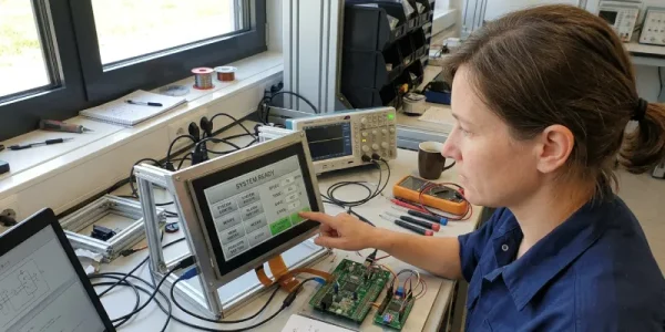
Here’s the misdiagnosis chain I see most often. An engineer reports “the touch screen stopped working.” The team assumes it’s a firmware bug. They reflash the GUI project. Problem persists. They blame the MCU UART library. They rewrite the communication layer. Still broken. Three weeks later, someone finally checks the ambient temperature log and notices the failures cluster between 6 AM and 8 AM in January — exactly when the factory floor drops below 0°C.
That’s a typical four-step misjudge chain: software bug → firmware bug → communication bug → finally, environment.
Environmental Failures
Cold is the most underestimated killer. TFT LCD response time slows measurably below 0°C. At -10°C, resistive touch layers can delaminate at the bonding edge if the original adhesive spec wasn’t rated for thermal cycling. At -20°C, you start seeing LCD contrast shift that operators interpret as screen damage.
Heat is the other side. Above 70°C continuous operating temperature, the backlight driver IC degrades faster than the rated MTBF predicts. I’ve measured 30% luminance drop after 2,000 hours in a 65°C enclosure — on a panel rated to 70°C. The rating is a ceiling, not a target.
Moisture doesn’t usually kill a display directly. It kills the connector. Condensation accumulates on the FFC cable between the main board and the LCD, causes intermittent signal loss, and the symptom looks exactly like a communication error. You’ll chase UART baud rates for a week before you check the physical connector.
Vibration breaks connectors too, but over months, not days. EV chargers mounted near compressors, elevator panels, and industrial machinery are your highest-risk environments. Specify modules with locking connectors or use conformal coating on the FFC interface.
Integration Failures
The single most common UART integration error: mismatched baud rate with no error detection. The MCU sends at 115200. The module is set to 9600. The display shows garbage characters or freezes. Both sides are functioning correctly — they’re just not speaking the same rate.
Inadequate power supply is next. Most HMI modules draw a startup current spike that’s 2–3x the steady-state current listed in the datasheet. If your power supply has poor transient response, the display resets during boot. Engineers see this and think the module is defective. They’re not wrong that something failed — they’re wrong about what.
Capacitive touch false triggers almost always trace to grounding. Floating ground planes create a capacitance reference that the controller misinterprets as finger input. If your application uses a capacitive panel and you’re seeing phantom touches, check the ground before you call the supplier.
Selection Failures
Specifying by screen size and resolution without checking the brightness rating is a frequent procurement mistake. A 400-nit panel looks fine in a dim warehouse. Put it in a cabinet with a transparent door facing a window, and operators can’t read it by 10 AM. Industrial outdoor-facing applications need at least 700 nits. Direct sunlight requires 1,000 nits or more.
IP rating mismatches matter similarly. IP54 keeps out splashing water. IP65 handles water jets. If your enclosure gets hosed down during cleaning cycles — common in food processing, medical equipment assembly, and EV charging stations in coastal cities — IP54 will fail within months.
How to Choose the Right HMI Display Touch Screen
Application Requirements First
Before you look at specs, answer these four questions:
What is the operator doing? Data entry tasks need a larger touch target area and better resolution. Monitoring-only panels can go smaller. Full process control interfaces need larger screens with clear visual hierarchy.
What MCU are you using? This determines which communication interface you need — UART TTL, RS232, or RS485. Don’t start with the display spec and work backwards to the MCU. Lock the MCU first.
Where will the panel be mounted? Recessed panel mount, open frame, or enclosed standalone unit. Each has different IP rating implications and different mechanical stress profiles.
Who is operating it? An engineer in a lab uses a panel differently than a gloved factory worker or an outdoor kiosk user in rain.
Environmental Specification Checklist
This is the section I wish someone had handed me on my first industrial project. Run through this before you finalize a display selection:
- Operating temperature: confirm the minimum, not just the maximum. Night-time temperatures in unheated facilities can be brutal.
- IP protection rating: IP65 as the floor for anything that will see liquid contact. IP67 for submersion risk.
- Brightness: 400 nits minimum for indoor industrial. 700+ nits for any ambient light above 500 lux. Measure your environment.
- EMI/EMC: if the display mounts near a motor drive, inverter, or welding equipment, confirm the module has passed CE EMC testing — not just CE safety.
- Vibration spec: check the IEC 60068 test report if it’s available. Ask for it if it isn’t.
Development Cost Is Part of the TCO
A module with free GUI design software saves your engineering team 3–5 working days per project. That’s not marketing — it’s an actual labor calculation. If you’re building custom UIs for 10 different clients per year and the software license for an alternative platform costs $800/seat plus a development learning curve, the math on an all-in-one module with bundled software closes quickly.
Ask the supplier: Is the GUI software free? Is it Windows-only? How is the project file loaded onto the module — SD card, USB, or UART? What happens when a new engineer joins the team and needs to modify a deployed project?
Two Industry Cases Engineers Don’t Talk About Enough

Case 1: The EV Charger Temperature Trap
EV charging stations look like a straightforward HMI application. The interaction is simple: select charging mode, authorize payment, monitor progress. Most teams spec a capacitive panel because it looks clean and modern. Then they deploy in northern markets.
The problem isn’t the cold temperature alone. It’s the thermal cycling. A charger in an outdoor parking lot goes from -15°C overnight to 45°C on a summer afternoon inside the enclosure when the sun hits the metal housing. That’s a 60°C daily swing. Over 200 cycles — roughly one season — the capacitive touch controller’s calibration drifts. The touch registration shifts by 3–5mm from the actual button position. Users tap “Start” and hit “Cancel.” Complaints come in. The operator assumes firmware. The firmware team finds nothing.
The real fix: either switch to a resistive panel with a sealed bezel, or use a capacitive module with an extended temperature range and build in automatic recalibration on boot. Some modules support a capacitive recalibration command over UART — most teams never use it because it’s buried in the datasheet.
Case 2: The Intelligent Locker Latency Misread
A logistics company was deploying intelligent parcel lockers across a city — 200 units in year one. The HMI requirement seemed simple: show a keypad, accept a 6-digit code, release the lock. They specced a capacitive touch panel, 7-inch, 1024×600. Beautiful unit.
Field reports started coming in after month two. “The locker didn’t open.” Support pulled logs. The touch input was registering fine. The UART command to the lock controller was being sent. But 1 in 80 unlocks was failing.
The diagnosis took six weeks. The culprit was command collision — the HMI was sending the unlock command on the same UART line that was also receiving temperature sensor data from the lock body. Under specific timing conditions, the two packets overlapped. Nobody had tested this during integration because the lab didn’t have the temperature sensor hooked up during touch testing.
The fix was a 50ms delay between touch event and command send, plus a hardware flow control line. Two lines of MCU code. The integration checklist should have caught it — but the team was using a consumer-grade development checklist, not an industrial one. That’s the real lesson.
How to Test Before You Deploy at Scale
Don’t test on the bench under lab conditions and call it done. Test where the unit will actually live.
Touch accuracy and linearity: Run a 5×5 grid calibration test. Tap each intersection point and log the reported coordinate. Acceptable deviation for an industrial panel is ±2mm. Consumer-grade panels can drift to ±4mm or more at the edges — which is fine for a smartphone, not fine when the operator is hitting a 10mm button target on a 5-inch lcd display.
Thermal cycling: The IEC 60068-2-14 standard defines the protocol. Minimum spec for outdoor industrial applications: -20°C to +70°C, 50 cycles, 30-minute dwell at each extreme. If your supplier can’t provide a test report to this standard, request sample units and run the first 10 cycles yourself before committing to a production order.
UART communication stress test: Run the display at full UART throughput — sending UI commands and receiving touch events simultaneously — for 72 hours continuous. Log every UART error. A good industrial module should show zero checksum errors in 72 hours under 25°C lab conditions. If you see errors, find out why before you scale.
Brightness measurement: Use a luminance meter (Konica Minolta CS-100A or equivalent) to measure actual panel brightness at center and at four corners. Corner brightness below 80% of center brightness indicates backlight uniformity problems that will be visible in field use.
The 10-point pre-production checklist:
| Check | Pass Criteria |
|---|---|
| Touch linearity across full screen | ±2mm deviation maximum |
| Touch response under glove (if required) | Consistent detection, 0 misses in 50 taps |
| UART error rate at max throughput, 72h | Zero errors |
| Cold soak boot test at minimum rated temperature | Boots and displays correctly |
| Brightness at 4 corners vs. center | ≥80% uniformity |
| IP rating verification | Water ingress test per stated IP level |
| EMI baseline test near intended equipment | No display corruption or resets |
| MTBF documentation from supplier | Report available and reviewed |
| GUI project reload procedure confirmed | Can reload without factory tools |
| Firmware version and update path documented | Version logged, update path confirmed |
How to Source a Reliable HMI Display Touch Screen
What the Supplier Tells You vs. What to Actually Verify
Supplier says: “CE certified.” Ask for the specific test report number and verify the issuing lab is accredited. CE self-declaration exists — it’s legal, but it tells you less than a third-party lab test.
Supplier says: “Supports all MCUs.” Ask for working code examples for your specific MCU. Not pseudocode — actual tested code. If they can’t provide it for your platform, that’s a red flag.
Supplier says: “Free software.” Ask whether it runs on your OS version, whether there are feature limitations in the free tier, and whether the project file format is documented so you’re not locked in.
Evaluating Chinese HMI Display Touch Screen Manufacturers
China-based lcd panel manufacturers supply the majority of industrial TFT LCD modules globally. The supply chain advantage — component access, tooling infrastructure, scale — is real and worth engaging with. The evaluation criteria matter more than the geography.
Look for: factory certification (ISO 9001 minimum), in-house test lab, English-language documentation, and a sample policy that doesn’t require a minimum order. A manufacturer that won’t send you a $60 sample before you commit to 500 units is telling you something about their confidence in the product.
Red flags: no English datasheet, no GUI software available for download before purchase, no response to technical questions within 48 hours, no CE/FCC/RoHS documentation available on request.
STONE Technology — 14 years, 3000+ industrial deployments — publishes full datasheets, provides free GUI design software (STONE Designer), and supports UART integration across every major MCU platform. Their V-series modules (STWI industrial / STWA advanced / STWC civil) are worth evaluating specifically because the product line matches different IP and temperature requirements without requiring custom orders at reasonable volumes.
Factory vs. Trading Company
A trading company can get you samples faster. A factory can modify the bezel color, logo, or panel size when your volume justifies it. The practical answer for most teams: use a trading company to evaluate three or four module options, then go direct to the factory for the one you standardize on.
How to verify factory status: ask for their ISO certificate with the issuing body clearly listed (not self-issued), request a factory audit report from a third party (Bureau Veritas, SGS), or arrange a video walkthrough of the SMT line. A legitimate factory will accommodate this. A trading company will stall.
The Principle Behind the Selection
The best HMI display touch screen isn’t the one with the highest specs on paper. It’s the one that survives your environment, integrates cleanly with your MCU, and can be supported by your team without a six-month learning curve.
Three things that matter more than most engineers realize until after a failed deployment:
Match the touch technology to the actual use environment — not the ideal one. Factor in gloves, liquids, temperature swings, and lighting before you finalize the spec.
Test under real conditions before you scale. Lab results and field results diverge more than most product managers expect. One unit in the real environment for three weeks tells you more than 50 units on a lab bench.
Choose a supplier who functions as a technical partner. The hardware is only part of what you’re buying. Documentation quality, software tooling, and support response time determine how much of your engineering hours go into integration versus firefighting.
Where to Go From Here
If you’re an engineer still in the integration phase: pull the UART timing logs before you change anything else. Most “display problems” in the first 30 days are communication configuration issues, not hardware failures. Check baud rate, check power supply transient behavior, check ground continuity. Then check the environment.
If you’re a project manager or decision-maker in the delivery pressure phase: repeated field failures after a hardware freeze usually signal a selection mismatch that won’t be solved by incremental firmware updates. At that point, the faster path is an external engineering review of the full hardware stack — not more internal debugging cycles. The cost of one week of external support is almost always less than two months of lost field credibility.
Request samples from your shortlisted suppliers before committing. Run the thermal cycling and UART stress tests in parallel. The 10-point checklist above takes about two weeks to run properly. That two weeks is worth more than any datasheet comparison you can do at a desk.